Background
The TopoDOT® application offers the capability to import calibrated images and map the image pixel orientation to the perspective view of the selected MicroStationTM view. This unique tool makes it possible to overlay extracted CAD elements over the image in the selected view with very high precision thereby employing this image information as a reference in feature identification.
TopoDOT® places specific requirements on the calibrated image if this feature is to be successfully employed. These requirements can be summarized briefly as:
- Camera/Lens model (unique to each camera/lens pair for best results)
- Camera Location (project coordinates for each image)
- Camera Orientation (defined with respect to project reference frame)
The responsibility for providing the tools necessary to extract this information lies with the system manufacturer. The operator should follow manufacturer’s process procedures necessary to acquire this data efficiently and accurately.
Certainty 3D will cooperate with any manufacturer to import their specific file formats. As increasing numbers of manufacturers add such calibrated image capability to their systems or individual operators attempt to develop their own solutions, Certainty 3D has seen a need for an “open” format to support our customers and the industry. This document identifies and explains the file format necessary for effective application of this unique TopoDOT® feature.
Image Project File (*.iprj)
The image project file contains information pertaining to the project directories, units, and available cameras.
[Image Project]
Version=2
Units=sf
RotationOrder=6

CameraCount=1
Name0=Camera 1
ImageDirectory0=.\
CalFile0=.\camera1.cal
[Image Project] – Header required for the file.
Version – Current version of the file format. Use value of 2
Units – Units in which the coordinates are specified in the image project.
Valid values are:
- sf – Survey Feet
- f – Feet
- m – Meters
RotationOrder – Documented value of 6 allows for the transformation matrix of each image to be directly specified in the image list file. Other values are no longer supported.
CameraCount – If multiple camera calibrations are available, set this value to the total
number of cameras in the project. For each Camera, there must be a Name and CalFile associated with it.
Name(index) – Name of the camera calibration
ImageDirectory(index) – Each calibration file may contain a unique directory. This
directory is a relative path from the location of the image project file to the
directory where all of your images are located. This may be left as “.\” if you wish to define the directory per image in the Image List file below.
CalFile(index) – Relative path from the location of the image project file to the location of the camera calibration file.
Camera Calibration File (*.cal)
The camera calibration file contains distortion coefficients and intrinsic properties of the camera used by TopoDOT to remove distortion of the images on the fly. It is important to note that should the images provided with the image project already have their distortion removed, the radial and tangential distortion coefficients (k and P values) should be set to 0.
[Calibration]
Version=2
Type=1
dx=8.4E-6
dy=8.4E-6
Nx=4256
Ny=2832
fx=1689.97897707826
fy=1691.03752169727
Cx=2122.84859490073
Cy=1432.31598208073
k1=0.00403931369502396
k2=-0.0754263253765206
k3=-0.0852103024783204
k4=0.121648640543892
P1=-0.00028428014657276
P2=8.05378517964374E-5
[Calibration] – Header required for the file.
Version – Current version of the camera calibration file. Use value of 2
Type – Type of Lens used. Valid values are:
- 0 – Normal Lens.
- 1 – Fish Eye Lens
dx – Dimensions of a single pixel of the CCD sensor in meters. Value is typically specified by the manufacturer.
dy – Dimensions of a single pixel of the CCD sensor in meters. Value is typically specified by the manufacturer.
Nx – Number of pixels in the horizontal direction.
Ny – Number of pixels in the vertical direction.
fx – Focal length in the x direction. The parameters fx are normalized by the pixel size. fy – Focal length in the y direction. The parameters fy are normalized by the pixel size.

fx......[pix]
f........focal length [m]
dx.....[m]
Cx – Principal point in the x direction.
Cy – Principal point in the y direction.
k1 – Radial distortion coefficient.
k2 – Radial distortion coefficient.
k3 – Radial distortion coefficient. Used for higher-order modeling of the radial distortion.
Value of 0 is valid.
k4 – Radial distortion coefficient. Used for higher-order modeling of the radial distortion.
Value of 0 is valid.
P1 – Tangential distortion coefficient.
P2 – Tangential distortion coefficient.
Camera Location/Orientation
The image list file contains all images tagged with the camera location, orientation and filename as shown below. It is important to note that the camera location must be in the overall project coordinate system. Similarly, the orientation must be referenced to the project coordinate axes.
Image List File (*.lst) – Version 1
[Image List]
Image=image0.jpg
Xyz=302080.545548 65029.935632 106.612940
Mat=-0.399553 -0.000395 0.916710 -0.916698 -0.005088 -0.399549 0.004822 -0.999987 0.001671
Camera=0
Image=image1.jpg
Xyz=302080.545548 65029.935632 106.612940
Mat=0.399553 0.916710 -0.000395 0.916698 -0.399549 -0.005088 -0.004822 0.001671 -0.999987
Camera=0
Image=image2.jpg
Xyz=302080.545548 65029.935632 106.612940
Mat=0.399553 -0.000395 -0.916710 0.916698 -0.005088 0.399549 -0.004822 -0.999987 -0.001671
Camera=0
[Image List] – Header required for the file.
Image – Filename for the image which is appended to the cameras ImageDirectory property. Optionally, the image path may be prefixed with a relative directory for accessing the imagery. Example: .\TrackA\DSC_0044.JPG
The image must be in either a JPG, JPEG, or PNG file format.
Xyz – Coordinates of the camera sensor at the moment the image was taken.
Mat – Rotation matrix defining the orientation of the camera at the moment the image was taken. The matrix values are specified as space separated values. r1c1 r1c2 r1c3 r2c1 r2c2 r2c3 r3c1 r3c2 r3c3
The final transformation should be defined such that the axes are oriented as show in the following image: http://www.certainty3d.com/pdf/technotes/OpenImageFormat_ImageOrientation.jpg
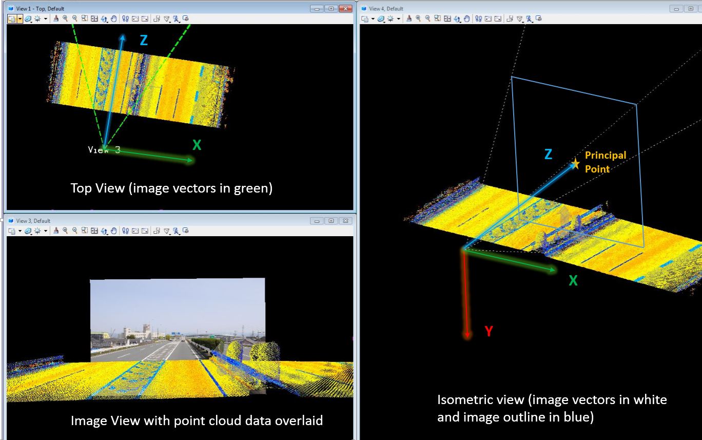
Camera – Index for the camera calibration to use for the image.
Requirements
Calibrated images combined with point cloud data greatly improve the productivity and quality of the extraction process. Typically, a user simply clicks on a point and TopoDOT will search through thousands of images to quickly find the closest image and import it automatically. Once the image is loaded, the user is able to switch between cameras to view adjacent areas. TopoDOT® users continuously exploit the detail in high resolution calibrated images to identify features and assets within the point cloud. Thus maintaining an organized image project format is imperative for overall process performance.
In order to effectively identify and locate the images closest to the selected location, TopoDOT® places specific requirements on how the image project (*.iprj) should be exported.
- There should be only one camera calibration (*.cal) for each physical camera in an image project (*.iprj, *.lst).
- Failure to do so will result in users being unable to distinguish between the same cameras defined in other locations.
- Image list file (*.lst) should maintain the same file name as its parent image project file (*.iprj).
- This allows TopoDOT to automatically locate the image list file (*.lst) and not require an additional selection from the user.
- All tracks\trajectories\setups should be exported into a single image project (*.iprj, *.lst)
- Failure to do so will require the user manually select each file or run a separate merging operation. This also complicates the TopoDOT® process for automatically reprojecting CAD elements to adjusted point clouds when using pre- and post-adjustment camera orientation files as the process input.
- In the event that separate image projects (*.iprj, *.lst) must be created and the camera calibrations (*.cal) have not changed, the camera calibration files should be recycled from the same location.
- Failure to do so will result in users being unable to distinguish between the same cameras in different tracks\trajectories.
Example Image Project Directory Structure*Note that highlighted labels are directory names.
- Project
- FrontLeft.cal
- FrontRight.cal
- RearLeft.cal
- RearRight.cal
- Image Project.iprj
- Image Project.lst
- TrackA
- Jpegs
- TrackB
- Jpegs
- Track–
- Jpegs
- TrackA
Please contact your TopoDOT support team for any further information.
1 Comment
Balint Vanek · September 17, 2020 at 12:08 PM
It would be nice to know how these coordinate systems are defined, with respect to the photogrammetry PATB system (https://support.pix4d.com/hc/en-us/articles/202558969-Yaw-Pitch-Roll-and-Omega-Phi-Kappa-angles)
Here it seems like roll happens around the East-West axis and pitch around a North-South axis suggesting an East-North-Up (local) coordinate frame.